flexar Continuous Level
<<< Back to Solid Level Sensors
 |
|
Principle of Operation
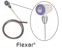
Flexar® smart guided wave radar level sensors and transmitters operate using TDR (time domain reflectometry) principles that were first developed in the middle part of the 20th century for use in the geological field. Further development of TDR led to its use in the telecommunication industry for detecting breaks in cables. Flexar technology was pioneered in the mid-late 1990’s when TDR was applied to level measuring applications within the process measurement industry.
In the application of TDR for process level measurement micro-pulses are continuously transmitted along a probe or “wave guide” at the speed of light. As soon as the pulses reach the material surface they reflect back to the sensor electronics unit. The time-of-flight of the pulses is calculated and directly related to the distance from the point at which the sensor is mounted on the top of the vessel to the material surface (level). The output from the electronics is continuously updated as the level of the material surface changes

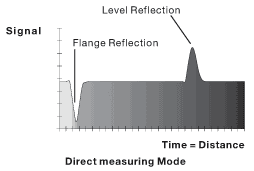
Flexar smart guided wave radar sensors are equipped with two different measuring modes. In the Direct measuring mode the pulses directly reflect off the material surface back to the electronics unit. This mode is used in applications where the material being measured has a dielectric constant as low as 2.1 for single-cable/rod probes and 1.8 for twin-cable probes.
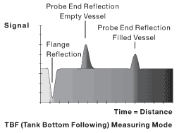
For materials with dielectric constant below the above mentioned limits, down to as low as 1.4, the second measurement mode is used. This is the TBF (tank bottom following) mode, which is used due to the inability of the pulses to adequately reflect off of the surface of very low dielectric materials. In this measuring mode the Flexar sensor has a “short circuit” at the bottom of the probe at a precisely known distance from the sensor’s mounting point.

In the TBF mode the pulses travel through air at the speed of light and then pass through the material in the vessel at a slower speed, dependent on the specific dielectric constant. The pulses are reflected at the short circuit back up the probe. Flexar sensors in the TBF mode measure the time between the emission and reception of the pulses from the probe short circuit. Because the return time of a pulse when no material is present (through air) is known, we can determine the difference in time between the time-of-flight when empty and the time-of-flight when filled as being directly proportional to the material level in the vessel.
 Download flexar Detail and Specification
 |
สอบถามข้อมูลเพิ่มเติมเกี่ยวกับสินค้า หรือปรึกษา Sales Engineer สามารถติดต่อได้ที่ Tel: 02 10 50 555 |